
TL;DR
While doing some reversing, I ran into a challenge that needed me to understand AVR architecture. At first, it really confused me, the instructions looked weird, the registers worked differently, and it just wasn’t anything like x86. I spent a few days feeling stuck.
So in this post, I’ll go over the basics of AVR, and show you how to set up an AVR dev environment using Atmel Studio 4.19 and HAPSIM on a Windows XP 32-bit virtual machine. Hope you enjoy the read 😄
Setup
Below are the tools and environment details used in this setup:
Windows XP 32 bits Virtual Machine
Atmel Studio 4.19
HAPSIM simulator extension
To briefly explain the programs, AVR Studio 4 is an AVR debugger, and HAPSIM acts as a terminal that can communicate with the application it analyzes as an AVR debugger.
Atmel Studio 4.19
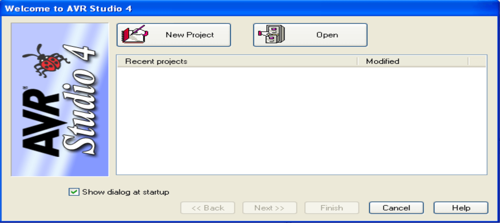
On the initial screen, click Open and select an existing ELF file.
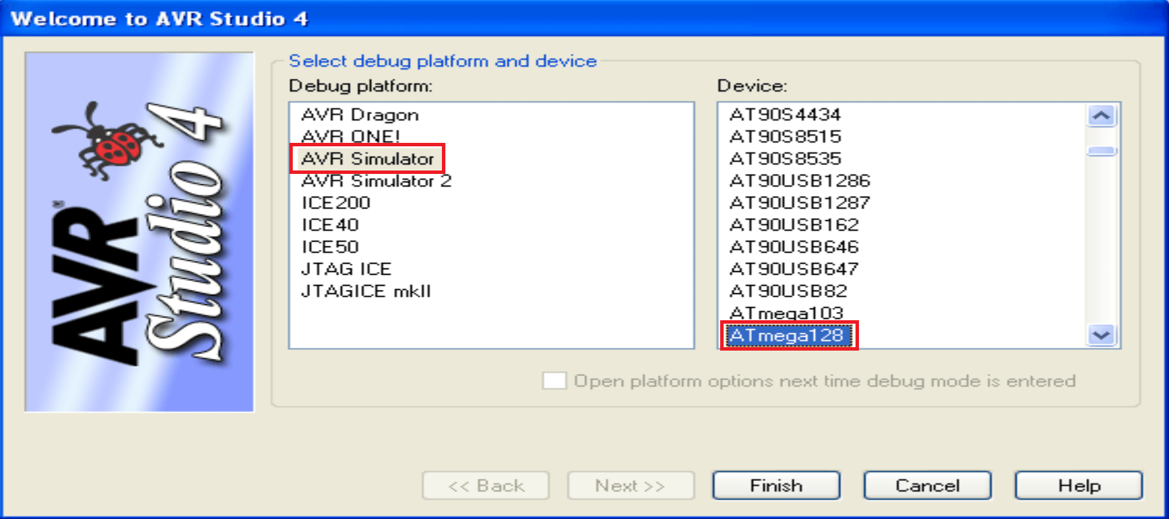
After that, choose the Debug platform and Device like in the following picture. I selected ATmega128.
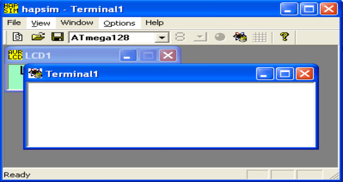
HAPSIM
Launch HAPSIM, go to File → New Control → Terminal.
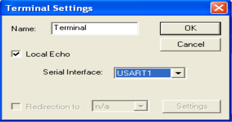
Then open Options → Terminal Settings. In the settings, check Local Echo, and select USART1, then click OK.
Result
Click Run in AVR Studio 4, the output as shown below.
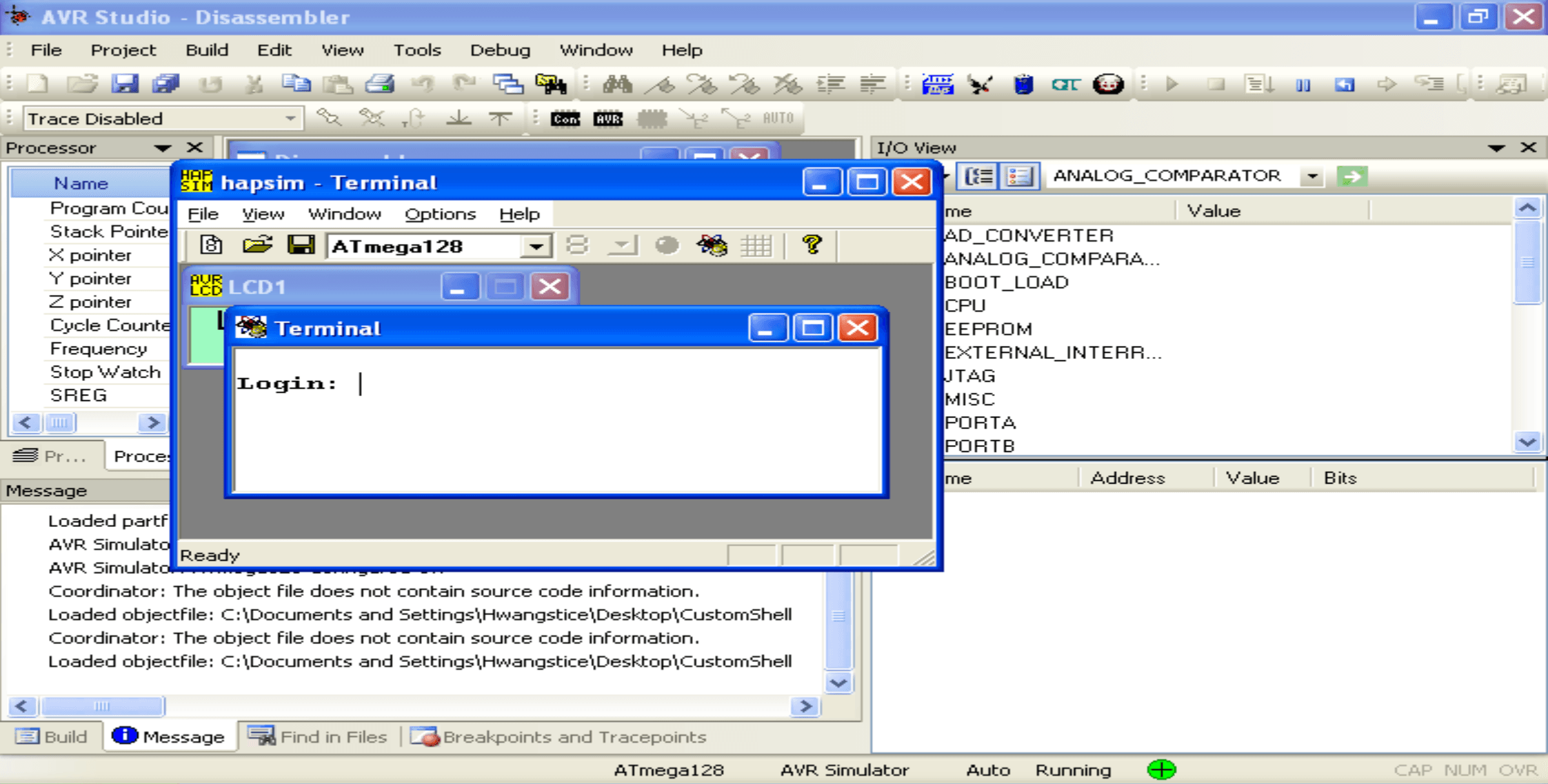
However, the first time I clicked Run, nothing showed up to the screen.
To make it work correctly, I had to first click Start Debugging in AVR Studio 4, then press Run again. Now, everything works fine.
Basics
AVR is short for Alf and Vegard’s RISC processor. It is an 8-bit microprocessor architecture developed by Atmel, widely used in embedded system. Compared to x86 and ARM, it has many unique and cool features.
Architecture
AVR uses Modified Harvard Architecture, which combines elements of both Harvard Architecture and Von Neumann Architecture designs.
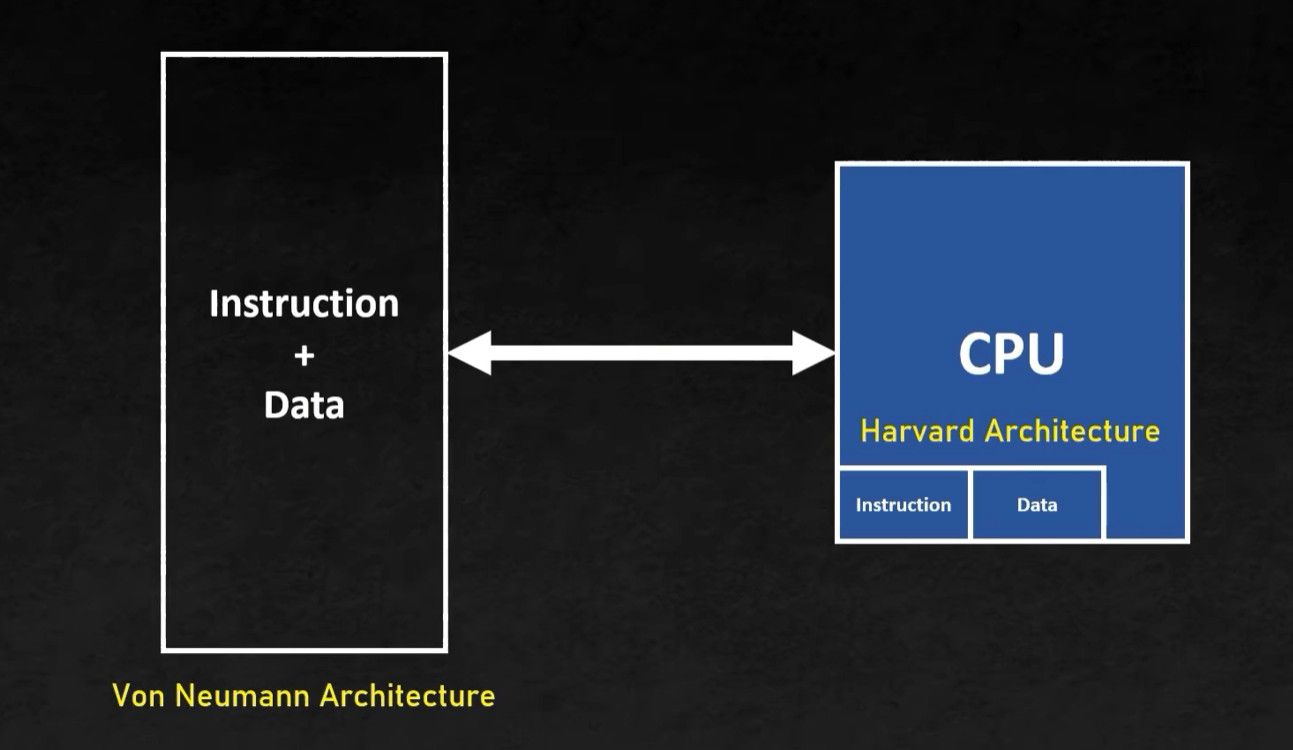
This makes AVR be super fast, resolve the problem of Von Neumann Bottleneck, and easily get access to data and instruction via cache in Harvard Architecture.
Data is checked in cache (Harvard Architecture) first. In an event of cache miss, RAM is accessed.
But what is cache? Why it is so crucial in AVR?
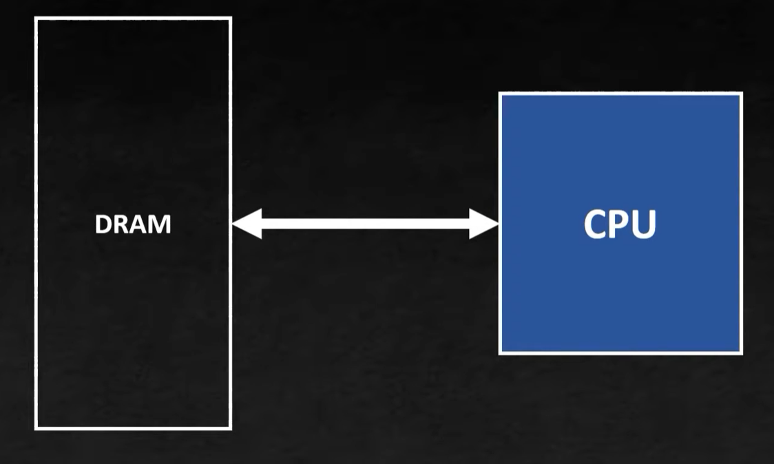
We all know that in modern world, CPU is at a level that it is exceptionally fast. But, most of the time, accessing the memory is longer than execution of an instruction.
This is because the shared memory is usually DRAM. It is cheap, but slower than SRAM, which means higher access time. Eventually, all of this affects the throughput. So, the CPU spends motst of its time waiting for the data to arrive.
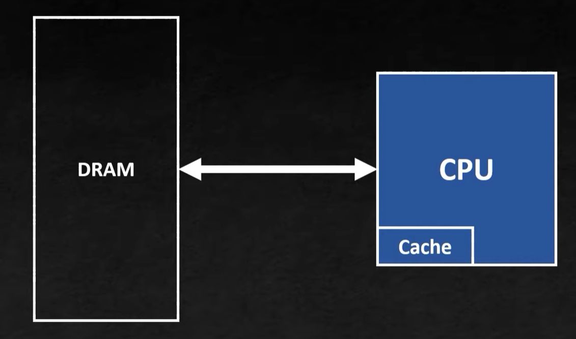
One solution is to use SRAM. It is much faster than DRAM, but it is costly. Thus, the CPU uses only a small amount of SRAM to quickly store and get access to most frequently used data. This small space is refered to as cache.
Register
AVR has 32 general-purpose registers (r0 to r31), memory-mapped to addresses 0x00 to 0x1F.
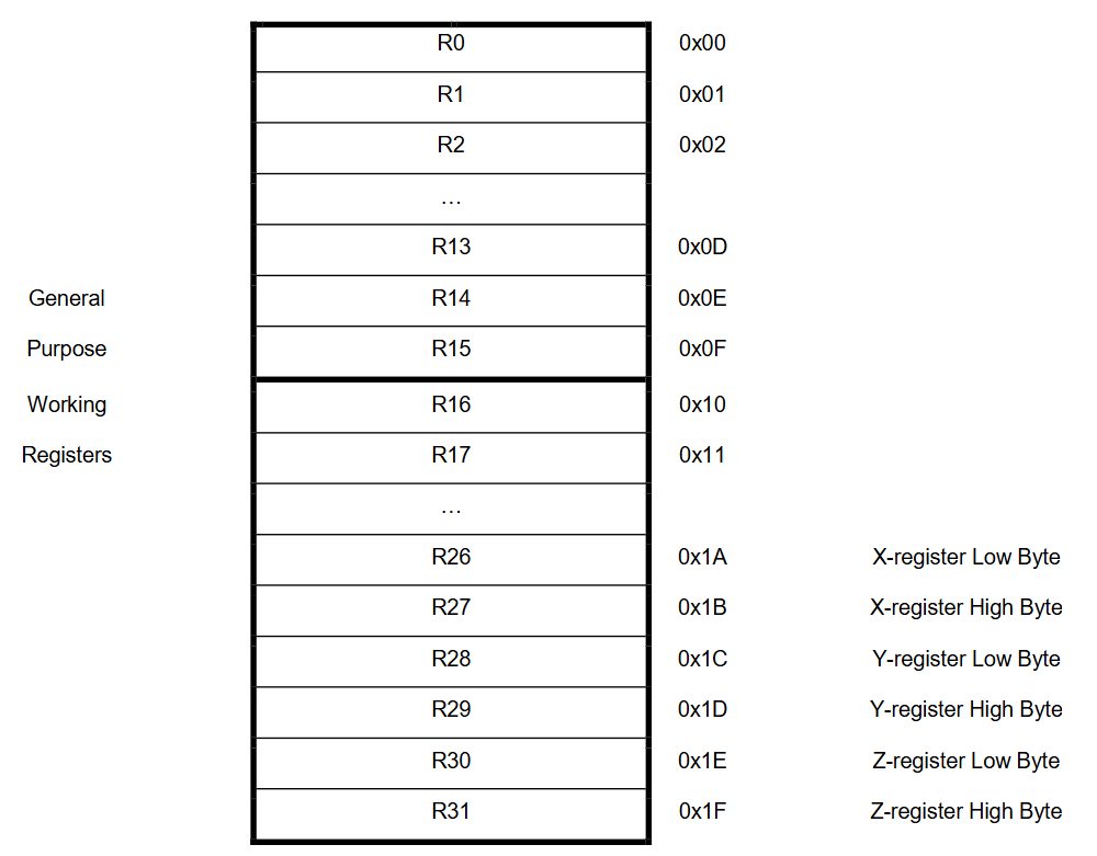
Register pairs:
r27:r26→ X register (16-bit, withr27as the high byte)r29:r28→ Y register (used as a stack frame pointer, likeebpin x86)r31:r30→ Z register (used for reading program memory)
Special rules:
r1is always0.Function arguments are passed through
r25:r24,r23:r22,r21:r20, and so on.Return values are stored in
r25:r24.
Special purpose registers:
SREG(Status Register): Similar to x86’s FLAGS, containing the sign flag, overflow flag, zero flag, etc., and updates automatically after operations. It is an 8-bit register.SP(Stack Pointer): Equivalent to x86’s ESP, 16-bit register.PC(Program Counter): a 16-bit register.
Memory mapping of special registers:
SREG→0x3FSPH:SPL(Stack Pointer High and Low) →0x3E:0x3D
Program Structure
AVR’s entry point starts with __RESET. Normally, in the first address of program (0x0000), there will be instruction jmp __RESET.
At __RESET, .data is loaded into SRAM, the value of SP (Stack Pointer) is initialized to the top of SRAM, then there is a call to main function.
Static Compilation
AVR programs are often compiled statically, meaning that the entire code, including library functions (like printf or scanf), is embedded into the binary. This contrasts with dynamic linking, where functions are loaded from shared library at runtime.
Since the compilation is static, the addresses of functions are resolved at compile time rather than at runtime. This allows the program to directly call functions like printf or scanf without relying on an operating system or dynamic loader.
Address Expression
Since the address space is 16 bits, two registers are used to express pointers. We have known that the AVR’s general-purpose registers are 8-bit, so two registers are combined to represent 16-bit pointer.
Also, register pairs like X (r27:r26), Y (r29:r28), and Z (r31:r30) are commonly used for pointer operations.
Here is a simple example, where I load value from memory location pointed to by the Z register pair.
LD R16, Z ; Load the value from the address in Z into R16→ This approach is essential for handling arrays, strings, and other data structures.
Function Call
Unlike x86, AVR does not push function arguments onto the stack. Instead, arguments are passed via register. Each argument is 16-bit, which needs two registers, and the order is as follow: r25:r24, r23:r22, r21:r20,…
Return value is also placed into r25:r24 (because there is always one return value!)
For example:
ldi     r20, 0xA
ldi     r21, 0           ; arg3 = 0x000A
movw    r22, r28
subi    r22, -1
sbci    r23, -2          ; arg2 = SP + 0x101
movw    r24, r28
subi    r24, -0xB
sbci    r25, -2          ; arg1 = SP + 0x10B
rcall   memcmp_8F5       ; memcmp(src, dest, len)